

PROJECT SCOPE
This idea incorporates multiple facets of artificial intelligence and machine learning. The vehicle will be installed with an imaging system that will be constantly taking images and comparing them to your healthy ones on a server. In case of an emergency a hospital will have the ability to communicate directly with the vehicle to prepare the right medical attention required for you. The car becomes autonomous and send you to the nearest clinic.
The purpose of the project is to design and create a system that can be implemented within a car manufacturing design system and utilize the machine learning aspect. The system created will be capable of recording and providing timely access to crucial data in the design of automated cars.
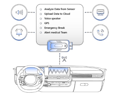
- As seen in the diagram, when the system being used on the test robot is used in a vehicle it will be able to will be able to:
- Analyze data from sensors which will be the non-visual data to be used in combination with the visual data coming from the images.
- Upload data and images to a cloud that will be used for analysis using pattern recognition. The new data will be analyzed against the pictures on the cloud already. Any new data will be analyzed and categorized.
- In case of danger, a voice speaker will be activated to alert the driver of what the system would have analyzed. This communication from the voice system will alert the driver of any precautions to take.
- GPS emergency signal is sent to the car manufacturer and server.
- In the case of an emergency, a medical team will be alerted so that they can be prepared to deal with the situation.
WHAT CAN YOU EXPECT FROM THIS NEW TECHNOLOGY?
- An autonomous vehicle is used as a training/test device before installation of technology into vehicles. Helps with road safety and fatalities if the system experiences any design flaws.
- This autonomous vehicle will be used to replicate the real-world scenario of what our vehicle system will face, basically it’s a simulator.
- A kit for installation on older vehicles that are not as technologically advanced can be sold separately.
Click on the video below ⬇️ and watch as I explain the genesis of the idea and the science behind it.
BUILDING OUR MECHANICAL DEVICES
There are several physical aspects of robotic manipulators that we will not necessarily consider when developing our autonomous vehicle based on mathematical models. These include mechanical aspects (e.g., how are the joints implemented), accuracy and repeatability, and the tooling attached at the end effector. We’re going to leverage these tools mathematically to develop a sound solution for our problem.
We need to start by identifying the type of device we need to solve our problem. For example, a hydraulic robot would not be suitable for food handling or clean room applications. Robot manipulators can be classified by several criteria, such as their power source, or way in which the joints are actuated, their geometry, or kinematic structure, their intended application area, or their method of control. Such classification is useful primarily to determine which robot is right for a given task.
Robots are often classified by application into assembly and non-assembly robots. Assembly robots tend to be small, electrically driven, and revolute like the one we are using for our solution. We’re going to use a rover robotic arm to maximize our potential in solving the solution.
APPLICATION AREA AND DESIGN
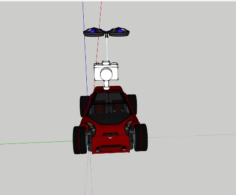
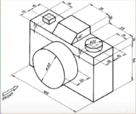
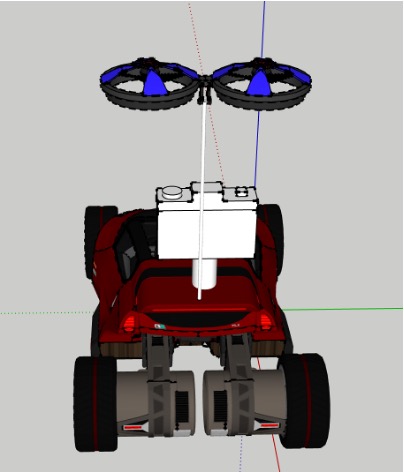
We made some modifications to our autonomous robot to fit our specifications. As we will see on the final design done using SketchUp, a camera was added, propeller blades to be used in airlifting, and different composite material used for durability, sustainability, and cost effectiveness.
METHOD OF CONTROL

Our device is classified by control method which uses closed-loop computer control to determine the motion and are thus capable of being a truly multifunctional, reprogrammable device. Servo controlled robots are further classified according to the method that the controller uses to guide the end-effector. The simplest type of robot in this class is the point-to-point robot. A point-to-point robot can be taught a discrete Set of points but there is no control on the path of the end-effector in between taught points. Such robots are usually taught a series of points with a teach pendant. The points are then stored and played back.
SYSTEM AND CONCEPTUAL SKETCHES
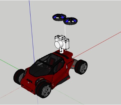
Our vehicle is built with propeller blades that will be used when the vehicle goes into emergency mode. A camera to constantly improve our simulation method for machine learning. A light vehicle measuring about a third of a full-sized EV sedan both in mass and dimensions. (Figure of the conceptual sketch)
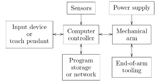
Even the programmed software should be considered as an integral part of the overall system, since the way the robot is programmed and controlled can have a major impact on its performance and subsequent range of applications. (Figure: Components of our system)
SYSTEM AND DESIGN FEATURES
We want to build a system which uses a pattern recognition system for a camera system which detects obstacles to determine if the car should break and/or manoeuvre. Thousands of hours of images for training the system so that the system can properly detect obstacles to an acceptable level in the training set. To achieve the level of accuracy required a few steps must be taken.
- A method of evaluation of this system with a data set which is independent of the training set. This simply means you would need training systems with one data set and then evaluating them with another set which ideally should be larger and completely independent of the training set. This will allow you to see if a given (classification) system can generalize its (classifications) solution to data which is different from the training set.
- A training set that includes cases which the cars are encountering in the real world.
- An evaluation set should be independent of the training set to give a good evaluation measure. The evaluation set should also give good coverage of cases of interest in the real-world application.
CITATIONS
- UVIC ECE 485: January – April 2021 course notes and assignments
- M. Arbib. Computers and the Cybernetic Society. Academic Press, New York, 1977.
- H. Asada and J.A. Cro-Granito. Kinematic and static characterization of wrist joints and their optimal design. In Proc. IEEE Conf. on Robotics and Automation,, St. Louis, 1985.
- H. Asada and J-J. Slotine. Robot Analysis and Control. Wiley, New York, 1986.
- S. Barnett. Matrix Methods for Engineers and Scientists. McGraw-Hill, London, 1979.
- Jerome Barraquand and Jean-Claude Latombe. Robot motion planning: A distributed representation approach. International Journal of Robotics
- Research, 10(6):628–649, December 1991. G. Beni and S. Hackwood, editors. Recent Advances in Robotics. Wiley, New York, 1985.
- D. Bertsekas. Nonlinear Programming. Athena Scientific, Belmont, MA, second edition, 1999.
- William M. Boothby. An Introduction to Differentiable Manifolds and Riemannian Geometry. Academic Press, 1986.
- https://www.cnet.com/roadshow/news/heres-why-people-still-crash-with-driver-assistance-systems/
- https://www.seattletimes.com/business/boeing-aerospace/what-led-to-boeings-737-max-crisis-a-qa/
- https://blog.ml6.eu/how-to-choose-a-camera-for-ml-e2a1819f37e0